1. Modelling a basic tank for C&C 3.
A good target polygon count for a C&C3 vehicle is about 2500. I would aim for about 2000 since rigging later will add more to that count. Avoid getting too close to 3000 and don't waste polys in detail that is too small or wont be seen from the game angle. It's not that the engine can't handle a few extra polys in as much as it is in building up strong modeling skills. It's 'easy' to just pump out models without concern for optimalism, but that can result in degrading quality, performance issues and other visual problems. Remember in games these days the players can zoom in to take a look at your model, so take the time to make it a good one. Remember to trim, cut and clean up as you go to save polys for those last finishing details and also to avoid going over it all again to tidy up at the end.
Some things to watch out for while you're modelling:
- Coplanar faces, - this is when 2 or more faces occupy the same space on a surface. Not only an inefficient use of polys, but it causes surface shimmering and in some cases shadowing errors.
- Internal faces, - a surface inside an object that you wouldn't see from the outside. This could easilly be an accidently flipped face, which would look like a hole in the mesh from the outside.
- Non-closed surfaces, - sometimes you end up with a very fine gap between faces if you don't, or can't, weld them together. These line bleeds can cause smoothing and shadow problems.
So, let's start modelling. Here I'm going to make a Challenger 2 tank. Since I'm modeling a factual vehicle, there is a need for accuracy and detail. Making a model from "eyeballing" photos is not as easy it seems, so it is essential to get a 3-view blueprint drawing and use it in the modeling process. Also make sure you have plenty of photos at hand to refer to, just to check on any details that may not be clear in the drawing. A google image search for your chosen vehicle is usually good enough. To set up your 3-view drawing in Max is fairly straightforward.
Create a Plane in top view, 1 seg in length and width.
Open the Materials Editor and click the box on the right of the diffuse colour. In the Material/Map Browser, double click on Bitmap and navigate to your 3-view drawing.

Click the Show Map in Viewport button, and apply to selection.
Apply a UVW Mapping modifier to the plane. Drag the panel up a bit until you see the Bitmap Fit button. Click it, and select your 3-view drawing.
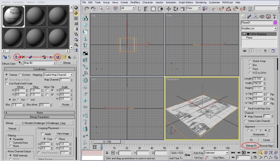
The image on your plane will now stay the same size, while you change the length or width of the plane.
Click on Plane under the UVW Mapping to adjust the length and width. If you need to move the drawing to centralize the top drawing on your plane, click the plus sign on the left of the UVW Mapping and select the Gizmo and use the Move tool.
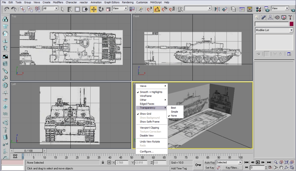
Now clone, rotate and adjust until your setup is like the following. Do your best to keep the drawings lined up (not all are 100% spot on) and set all viewports to Smooth and Edged Faces. I would also suggest setting your perspective viewport to smooth + highlights and turning off transparency.
Previous | Next
 - all rights reserved.